ELECTRONICS
The Electronics/Power team is in charge of converting the internal currents from the battery to all the other electronic parts in the robot! As the electrical team, we are in charge of creating the schematic that allows buck converters to function. Our main programs include KiCAD and EagleCAD. This year we switched over to KiCAD, which functions as a simpler program for our members to design and create schematics for our club. We also work with Printed Circuit Boards (PCBs) & Power Distribution Boards (PDBs).
Buck Convertor Introduction
Buck Converter Schematic Example -
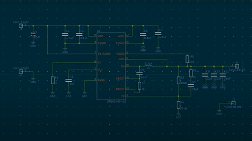
Buck Converter Tutorial!
We chose this tutorial to follow as it provided a thorough and easy explanation between what to choose and pin for a buck converter schematic. The tutorial goes over basic requirements that all schematics must have and then dives into the specifics for this example buck converter schematic. By following this video, members are able to learn the difference between voltage outputs when making a buck converter and the performance output that the different voltages give.